A customer approached us with a need for a connector that could be used in an implantable defibrillator. They needed six contacts that could each handle two amps at 1000 volts continuously. The connector would be welded inside of the titanium housing they were developing but their overall device was getting to be too long and so our connector needed to be as short as possible.
What it Looked Like
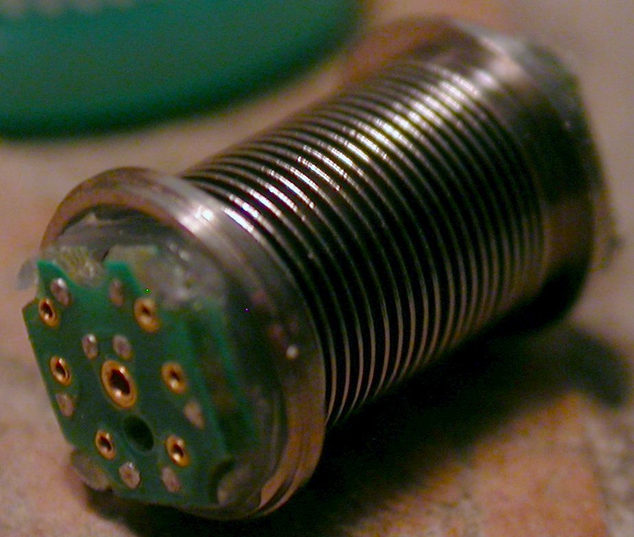
Design Details
The two driving factors in this design were the low profile (z height) and the high voltage potential between the pins. Handling the current wasn’t an issue. We knew from previous experience that it was possible to have as little as an 0.020-inch gap between conductive elements on a PCB and pass high potential voltage tests in excess of 1000 volts so that became our minimum standard. If you try this yourself, please note that this only works when you have good solder mask on the PCB, there are no sharp edges on the traces or solder joints, and everything is SUPER clean. Contamination is your enemy!
The welded titanium bellows that our connector had to fit into was only 0.250 inches in diameter. For simplicity in the final assembly it was decided to put female connectors on both ends of the bellows and plug the ridged sections of the rest of the finished device into those connectors. To meet our voltage requirement between the pins from the mating connector and the metal bellows we had to design a very thin (about 0.010 inches thick) nylon cup that went under the female connector. As we had to have it anyway, we used this cup for alignment, retention, dielectric and as a strain relief for the wires inside the bellows.
Speaking of the wires, they became a key component of the design in ways nobody suspected. First, the wires were custom made so that we could get a multi-stranded wire in the diameter we needed (I think it was made out of five strands of 52 gauge silver plated wire). The wire was then insulated with two different insulations which made it so that the wires could freely rub against each other and not fray or cause shorts later. Each wire had to be laser cut as that was the only way we could reliably get the exact length of wire in between the two connectors. Too much wire and the metal bellows stretched out and made the whole assembly too long. Too little wire and the strain on the short wires was too great and they broke under the extreme flex testing every bellows assembly had to undergo.
Making the PCBs was also more challenging than expected. We had to push our suppliers to the limits of what their machines could produce in multiple ways. Eventually, we had to buy more than we needed, carefully measure every board, and only use those that passed our internal inspection. This was expensive and time consuming, but it worked.
Conclusion
Having a customer push you to do more than you think you can do can be a wonderful thing. If they have pockets deep enough to pay for the development.
Through this project I was able to go to Costa Rica and set up a manufacturing line in another country. I was able to work closely with a lot of very talented engineers at many of our suppliers, solving one of the myriad of problems that came up during development. This project also made me realize how important Geometric Dimensioning and Tolerancing (GD&T) can be.
At the end of the day I made a product that worked and worked well. The customer liked it and it passed all their testing. We were able to produce our assemblies in a volume and timeframe that the customer was happy with and at a price they were willing to pay. Unfortunately, our customer ran out of funding before they could get out of animal trials and our connector never made it market.