Mechanical Use Limiter

What it Looked Like

Production verions of Mechanical Use Limiter mounted to a PCB
The black plastic bit is the body of the Mechanical Use Limiter

Design Goals

Medical devices are expensive, even for hospitals, and so there is always a strong incentive to clean and re-use even “single use” or “disposable” devices. Medical devices also have very stringent cleaning requirements and typically undergo autoclave, Ethelene Oxide, or E-Beam sterilization. The problem is that most devices were never designed to be compatible with an autoclave (the most common sterilization method for refurbishers) and were never designed to be cleanable. Blood could, and would, get inside of nooks and crannies of a device or seep inside of catheters and tubes, dry, and not be able to be removed.

As an autoclave involves very high temperatures and lots of steam it is not suitable for devices made from plastic, can’t get wet, or are hard to completely dry (like is the case when long catheters or other thin tubes are involved). E-Beam sterilization involves bombarding the device with lots and lots of radiation to destroy any bacteria and viruses that may be anywhere in the device or the packaging. This solves all the problems from the autoclave but requires that all the materials be very radiation stable and precludes the use of any kind of semiconductors (the radiation will destroy transistors and mess with any saved data in a device). Ethelene Oxide is a poisonous gas that packaged devices are pressure cooked in. The process is slow and expensive and requires the packaging to be somewhat porous which means that devices have a sterilization shelf life.

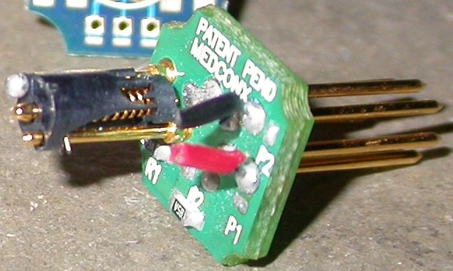
The Mechanical Use Limiter was designed for use with Ethelene Oxide and E-Beam sterilization. The device needed to have as small as possible a diameter but could be relatively tall as it was expected to be installed inside the electrical connector of a disposable medical device. Expectations were that 3 insertions of the electrical connector would be sufficient: once for final testing and QA of the finished device and two for use in the hospital.

Design Details

We knew that our customer was using some very specific connectors from LEMO and ODU as we were already making custom mating connectors for them. The custom connector platform was a natural place to locate the use limiter device. We also knew that our customer wanted to move to E-Beam sterilization as so that meant that all the normal electronic use limiting methods wouldn’t work.

As we studied the problem we realized that the machine that the disposable devices were plugged into performed some basic checks of the disposable device, in part to ensure that it knew which of the many supported devices was plugged in. Our solution, then, was to create a mechanical switch that, after a set number of activations, would change the ID value to one that didn’t follow the established ID spec. This caused the controller machine to display “Unknown Device” and refuse to supply power.

The tolerance analysis told us that the connector systems would ensure that there was between 0.020” and 0.125” of engagement between the male plug and the female receptacle. The use limiter was then designed to trigger at 0.015” of engagement and handle up to 0.140” of engagement. Meeting the lower end of this scale was challenging because the mechanical strength of the features in the materials we were looking at were very low at that small size.

The body of the use limiter was injection molded from Glass Filled Liquid Crystal Polymer (LCP). This material was a great choice because it is very liquid during the molding process, allowing for very fine feature resolution, has a high melting point which lets you solder near it, is basically impervious to water which let us use ultrasonic cleaning of the assemblies, and is one of the most radiation resistant plastics available.

To assemble the device, a gold plated beryllium copper spring is inserted through the wide opening in the side. A plunger is then inserted through the bottom of the housing, through the center of the spring, and finally out the top of the body. A barb system ensures that the plunger can be installed easily but is difficult to remove. At this point the spring can be manually wound to the starting position, the spring trimmed to length (the arms of the spring were longer than needed to make assembly easier) and set aside for later installation.

The install process was similarly easy and involved slipping the body of the limiter over two pins mounted on our custom connector platform. During soldering of other components onto the connector platform the tops of one of the pins was also soldered. The ball of solder on top of the housing was tested to be one of the strongest retaining methods and only added a few seconds to the assembly of the custom connector already being done. This method was also fully compatible with the existing cleaning process and so no added steps needed to be taken.

Conclusion

Even though it took a long time and many iterations to get right, the final result worked great, was easy to install, had a low Bill Of Material cost adder, and made the customer happy. We eventually added the use limiter to four other product lines from the same customer. Several patents were also created based on the design and development of the mechanical use limiter, giving both our company and our customer a competitive advantage.